Vessel
Vessel, current location, ETA, ETD / available attendance window and berth or anchorage if known.
PANAMA · ONBOARD ELECTRICAL TROUBLESHOOTING
VFD tripping, motor not starting, overload, soft-starter fault or an uncertain drive-to-motor problem? Send the fault code, equipment nameplate and vessel ETA. TESS reviews the supply–drive–motor–load chain before mobilization and prepares qualified onboard attendance in Panama.
Photos, nameplates, drive displays, drawings and fault history help us prepare. Do not send service passwords or access credentials.
A fault code alone rarely identifies the complete cause. Before attendance, send the available equipment information so the engineer can prepare for the installed system, possible interfaces and required diagnostic path.
Vessel, current location, ETA, ETD / available attendance window and berth or anchorage if known.
Affected machinery; VFD, motor, starter or soft starter; maker, model, power rating, voltage, frequency, motor kW and RPM where relevant.
Fault / trip code or alarm; when it started; permanent or intermittent; during start or under load; operational impact.
Equipment and motor nameplates, drive display, panel photo, electrical drawing, manual or previous service report.
Send what is available. Specialist details and attachments are optional.
A motor that does not start does not automatically have a motor fault. The problem may be upstream, inside the starter or drive, in the motor cable, in the motor itself, in the feedback system or in the driven machinery.
PLC / Local Control / Permissives → Starter / VFDPLC, HMI, remote I/O, software, control network and controller logic: PLC / HMI specialist support.
TESS conceptual diagnostic model. This is not a wiring schematic or a test sequence.
Ownership follows the failed function. Switchboard, feeder, breaker and distribution protection belong to upstream power diagnosis; starter, VFD, motor cable, motor, encoder and brake/control interfaces belong to drive and motor diagnosis. An unknown layer starts with broader troubleshooting.
A VFD fault code is evidence, not a complete diagnosis. TESS evaluates the drive together with its supply, command signals, motor circuit, feedback and mechanical load so that replacement decisions are based on the actual fault layer.
Maker/model, active code, fault history and available manuals. AC drives and relevant DC drives are assessed according to the installed equipment.
Input and control supply, local/remote state, start command, permissives, external interlocks, communication, feedback and drive status.
Output indication, motor current, cooling, fans, terminals and visible damage; motor cable / load-side isolation where technically appropriate.
Compare with approved configuration or an available backup. Configuration recovery and controlled changes follow authorization and manufacturer guidance, with an operational test after corrective work.
These are diagnostic categories, not reset instructions. The installed drive, operating state and available evidence determine which layers need investigation.
Load, motor, cable, configuration or drive.
Supply, deceleration/regeneration, braking circuit or drive sensing.
Incoming supply, connection, supply interruption or drive power circuit.
Motor cable, winding, moisture/contamination or drive output.
Motor duty, process load, brake, cooling or configuration.
Driven load, brake, motor, feedback or control configuration.
Airflow, cooling fan, ambient conditions, loading or drive condition.
Cooling, duty, load, phase condition or thermal feedback.
Supply, feeder, connections or input detection.
Motor cable, terminals, winding or drive output stage.
Supply, charging/power circuit, braking or internal drive condition.
Sensor supply, wiring, encoder, interface or configuration.
Network, communication module, PLC/controller or configuration.
Permissive, field device, wiring or control sequence.
Safety circuit state, interface or drive indication; safety integrity must be preserved.
Fan, supply, airflow restriction or monitoring circuit.
Drive power stage, motor/cable condition or associated protection; OEM assessment may be required.
Motor data, control method, backup compatibility or documented changes.
Local/remote selection, start/reference signal, control supply or PLC interface.
High motor current can result from an electrical motor defect, but it can also come from voltage imbalance, incorrect configuration, a brake that does not release, bearing or driven-machinery resistance, or excessive process load. Diagnosis must separate these causes before a motor is condemned.
Low insulation may involve moisture, contamination, the terminal box, winding or cable. Phase-to-phase and phase-to-ground condition, and a motor heater issue where applicable, are assessed within the safe test scope.
Voltage/current imbalance, phase loss or single phasing, incorrect connection, winding condition, mechanical binding, brake, process load and drive configuration can all contribute to overload.
Insulation testing is performed only after the connected drive or other sensitive electronic equipment has been safely isolated from the test circuit. Motor and cable conditions may need to be evaluated separately.
DOL, star-delta and reversing starters; contactors, overload and motor-protection relays, control transformers, soft starters and local motor-control panels.
Contactor not pulling in, chatter, damaged contacts, overload trip, missing control voltage, coil fault, auxiliary contact, timer, interlock or soft-starter trip.
Incoming supply, bus, feeder, breaker and distribution protection follow upstream power diagnosis. Starter, contactor, overload, control circuit, local/remote control and output to the motor follow drive and motor diagnosis. Ownership depends on the failed function, not the cabinet name.
Secondary checks may include encoder, tachometer or resolver where relevant, speed feedback, thermal sensors (PTC / RTD), motor brake, brake rectifier, brake-release circuit and brake/interlock interface. Scope depends on the installed system and available documentation.
A seized pump, overloaded compressor, jammed fan, gearbox resistance, seized bearing, brake that does not release or abnormal process load can trigger an electrical symptom. TESS can identify that the electrical system is responding to an abnormal mechanical load; the confirmed mechanical defect then moves to the appropriate machinery repair scope.
Generator-control faults can involve the generator controller, AVR or excitation system, electronic governor, generator breaker, switchboard protection, synchronization interface, or PMS / PLC logic. TESS routes the fault according to the layer identified.
Start with broader electrical / automation troubleshooting.
Identify the fault layer →Generator breaker, switchboard protection and distribution belong to upstream power support.
Switchboard & Power Distribution Support →Software, remote I/O, control network and controller logic belong to PLC / HMI support.
PLC / HMI / Control-System Support →Technical pre-assessment defines the OEM or specialist coordination required.
Send for Technical Pre-assessment →Drive and motor work is planned around vessel authorization, isolation, stored-energy hazards and protection integrity. Energized diagnostics are limited to justified measurements under the applicable procedure. Safety functions, overload protection and interlocks are not defeated to keep equipment running.
Vessel procedures, LOTO, stored DC-bus energy, unexpected start and rotating machinery determine the safe attendance scope.
Parameter changes are made only where authorized and technically justified. Material changes record the parameter, old value, new value, reason, authorization, technical basis and result.
Standard electrical diagnostic equipment is selected according to the fault scope. Manufacturer-specific software, communication interfaces and specialist test equipment are confirmed case by case.
Diagnosis defines the component and supply route before procurement. Availability and compatibility are confirmed for the installed system.
Complete VFD, keypad/operator panel, cooling fan, communication or I/O module, approved control module, braking resistor/chopper, reactor/filter, contactor or fuse.
Complete motor, fan, bearing where appropriate, terminal block, thermistor / PTC / RTD, encoder, brake/rectifier, heater or cable/gland components.
Contactor, overload relay, motor-protection relay, timer, auxiliary contact, coil, control transformer or soft starter.
Discontinued drives, missing spare boards/keypads, obsolete protocols, missing backups, incompatible successors, repeated failures, unsupported controllers and undocumented modifications may change the replacement path.
A replacement VFD is not selected by kW alone.
Same model or approved successor, with the installed configuration and interfaces verified.
Requires rating and interface verification before selection.
Requires controlled adaptation, documentation and commissioning.
Repair the identified fault where practical; secure support, backups and spares; upgrade the affected drive or motor control; modernize the wider installation only where justified.
Coordinating a drive lifecycle or broader modernization project? Retrofit & Modernization →
A short Panama call can still be valuable even when the complete repair cannot be finished immediately. The first objective is to establish the faulty layer, protect the vessel from incorrect component replacement and define the fastest technically sound next action.
Identification, fault history, nameplates, supply/control checks, measurements and initial layer isolation.
Deeper motor/drive separation, insulation diagnosis where appropriate, starter/control work, parameter review and functional test.
Cable/motor troubleshooting, drive replacement, configuration migration, encoder/brake investigation, OEM coordination and repeat operational testing.
Obsolete-drive retrofit, multi-drive replacement or motor-control modernization.
Planning bands, not completion guarantees. Actual completion depends on access, findings, parts, OEM requirements, vessel authorization and the available port-call window.
Proprietary interpretation, approved replacement, licensed software, specialist repair, factory configuration and proprietary parts.
Inspection, measurements, wiring tracing, fault capture, drive/motor separation, part identification, OEM-directed checks, replacement, authorized configuration loading, functional test and report.
Manufacturer-specific software, service access and licensed diagnostic tools are confirmed case by case.
Corrective work completed and the agreed function tested.
Faulty layer identified sufficiently to define the next action and remaining limitations.
Required component, compatibility checks and supply / OEM route defined.
Obsolescence or system condition requires an engineered project.
Published electrical, automation and vessel-management experience provides context for the team’s work. These cases are not presented as VFD-specific or motor-rewind projects.
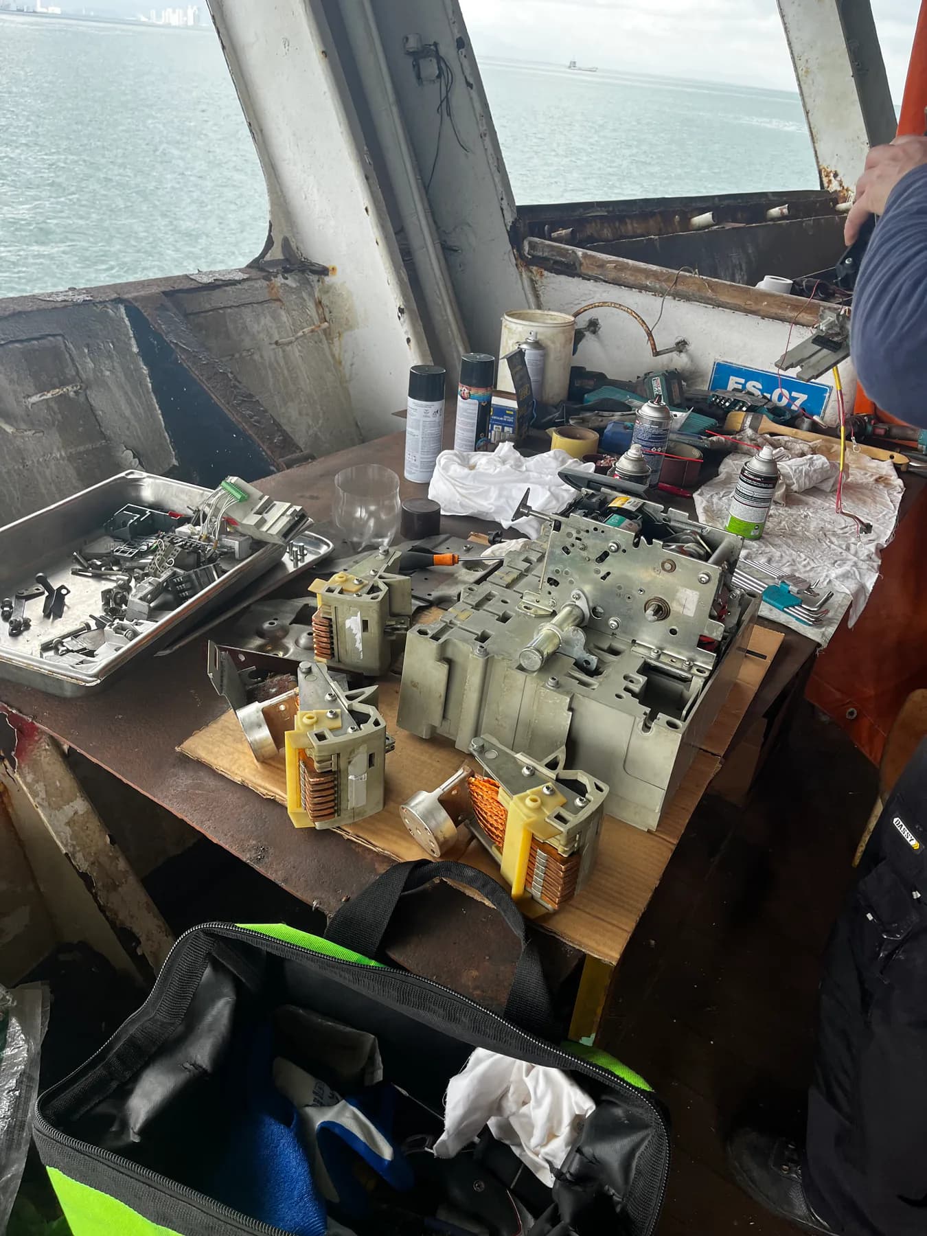
Published ongoing technical-management scope includes switchboards, distribution, automation and repair coordination. It supports system-level experience; it is not presented as a breaker-overhaul project.
See the technical-management scope →Electrical distribution and onboard control environments were reviewed during the broader multidisciplinary vessel assessment.
See the vessel-recovery assessment →Published lead-engineer experience connects control cabinets, electrical distribution and vessel systems. Historic work is attributed to the lead engineer’s experience.
See the lead engineer’s experience →Send what is available for technical pre-assessment. TESS reviews the installed equipment, fault and vessel window before confirming qualified onboard attendance and commercial arrangements. Equipment details and attachments are optional.
Yes, within a confirmed attendance scope. Send the fault history, display, nameplate and operating conditions. Repeated tripping requires investigation of the supply, drive, motor, commands and load rather than repeated resets.
No. Motor or cable condition, mechanical load, braking or configuration may cause a trip. The code helps direct the investigation; it does not by itself justify drive replacement.
Yes. Starting commands, supply, protection, starter/drive, motor cable, motor, feedback and driven machinery are considered within the agreed onboard scope.
That separation is the purpose of the diagnosis. Available evidence, isolation, access and operating conditions determine what can be established during attendance; intermittent faults may require further work.
Where technically appropriate and safely scoped. The drive and sensitive electronics must be isolated from the test circuit. Motor and cable conditions may need separate assessment.
TESS can assess an exact OEM replacement, compatible successor or engineered retrofit. Selection includes ratings, motor, controls, communications, braking, safety functions, dimensions and cooling, not only kW.
Only after compatibility, motor data and interfaces have been checked. An available backup supports controlled migration; configuration is not copied blindly. Changes require authorization, technical justification, documentation and testing.
Yes, subject to the installed equipment and documentation. Supply, commands, permissives, starter status, protection and motor/load condition guide the scope.
Yes. TESS can provide agreed onboard measurements and execution while the OEM handles proprietary interpretation or support. Software, service access and licensed tools are confirmed case by case.
Send ETA, ETD and the fault details before arrival. A short call may allow fault isolation and a defined next action even when parts or a full repair require a later window.
These are routed separately. Unknown faults start with broader troubleshooting; generator breakers and switchboard protection go to power support; PMS/PLC software goes to PLC/HMI support. Dedicated controller, AVR and governor interfaces require technical pre-assessment and OEM/specialist coordination.
TESS can diagnose the motor and, where required, define and coordinate an external workshop repair or replacement route.
Medium- and high-voltage drive or motor scope is assessed case by case according to voltage level, installed equipment, qualified personnel, vessel procedures and required specialist test equipment.
Send the fault code, equipment data and ETA. TESS can separate the supply, drive, starter, cable, motor, feedback and load, restore where practical, and define the correct repair, spare, OEM or retrofit path.