Vessel / schedule
Vessel, current location and ETA / requested attendance date first. Add ETD, berth or anchorage when available.
PANAMA CANAL · BALBOA / CRISTÓBAL · ONBOARD ELECTRICAL SUPPORT
Known fault in the main or emergency switchboard, breaker/protection, feeder or shipboard distribution? Send the fault indication, equipment details and vessel schedule before arrival. TESS reviews the technical picture, prepares the attendance scope and coordinates the appropriate onboard electrical support in Panama.
Useful before attendance: vessel location / ETA · affected switchboard or panel · voltage / frequency · breaker or relay model · trip indication · photos · single-line or electrical drawing if available.
A short technical review before attendance can save valuable vessel time. Send the schedule and the information already available onboard. The initial request does not need to be complete — photos, trip indications and the relevant drawing are often enough to start preparing the diagnostic path.
Vessel, current location and ETA / requested attendance date first. Add ETD, berth or anchorage when available.
Affected equipment, symptoms, operational impact and alarm or trip indication. Is the fault intermittent or permanent?
If known: voltage / frequency, AC/DC, panel, breaker or relay maker/model, feeder/load and shore-power, transformer or generator/bus involvement.
Photos, nameplates, relay displays, trip screens, single-line diagrams, electrical drawings, insulation readings, existing thermal images or previous reports.
A breaker trip is a symptom, not automatically a failed breaker. The device may be correctly interrupting an overload, short circuit, insulation fault or downstream cable/load fault. Protection operation, control voltage, an undervoltage release, trip circuit, interlock, mechanism or hot connection can also be involved.
This is a conceptual diagnostic map for qualified attendance. Replacement follows evidence; repeated resetting or bypassing protection is not a diagnostic plan.
The symptom may appear at the load while the fault is upstream — or the switchboard may be operating correctly against a downstream fault.
TESS prepares marine switchboard troubleshooting around the reported fault, installed equipment and vessel schedule. Qualified attendance connects the as-found condition with drawings and measurements before proposing marine switchboard repair, component supply or further specialist work.
Review available drawings, equipment labels, trip indications, control supply and operating history with the vessel team.
Voltage/frequency, current, phase sequence, continuity and suitable insulation measurements help distinguish source, bus, switching, feeder and load-interface faults.
Restore where technically possible, identify an affected circuit, specify parts or coordinate OEM support. Verify the agreed function after completed work where appropriate.
Personnel, access, isolation and diagnostic equipment are confirmed against the scope before attendance.
Incoming/outgoing feeders, bus-section and bus-tie status, breaker indications, control supply, closing/trip circuits, auxiliary contacts, interlocks and metering. Review voltage, frequency, phase condition, terminal damage and insulation concerns on suitably isolated circuits.
Normal and emergency incomers, transfer/changeover electrical interfaces, breaker/interlock circuits, control supply and essential outgoing feeders. Include emergency-generator connection and DC/charger interfaces where relevant.
Diesel-engine, fuel or cooling faults, mechanical emergency-generator overhaul and major alternator/excitation work require the relevant specialist scope. A confirmed controller/software issue follows the controller support path.
ACB, MCCB, MCB, isolator, changeover, contactor and starter faults can involve closing power, closing coils, shunt-trip circuits, undervoltage releases, auxiliary contacts, protection lockout, interlocks, worn mechanisms or thermal damage. A breaker that will not open needs the same disciplined scope assessment as one that will not close.
TESS can diagnose breaker and switchgear faults onboard, check associated control and protection circuits, replace identified components where technically appropriate and available, and coordinate specialist workshop/OEM testing or breaker replacement when the identified scope requires dedicated equipment or procedures.
Review relay maker/model, trip/event indications, control supply, trip circuit, breaker relationship and CT/VT interface wiring where appropriate. Overcurrent, undervoltage, overvoltage, phase loss/imbalance or reverse-power indication at the generator/bus interface may reflect an actual system fault. Compare installed settings with approved documentation where available.
Setting changes require vessel authorization, correct system information and an engineering/OEM basis. Record old/new values, reason, authorization and appropriate verification. Specialized relay testing, injection testing or protection studies are confirmed separately when the identified scope requires dedicated equipment or specialist engineering.
Qualified investigation confirms the indication, identifies the distribution section and assesses feeder isolation where operations permit. Cable and load boundaries, suitable isolated-circuit testing and inspection help define repair, isolation or the next action. Intermittent faults may need further monitoring or access.
Insulation-resistance testing must only be applied to a suitably isolated circuit. Sensitive electronics and solid-state equipment such as PLCs, VFDs, UPS units, electronic power supplies and similar connected equipment must be isolated as required before insulation-test voltage is applied.
Power loss at the machinery does not automatically mean the machinery itself has failed. The diagnostic path should establish where healthy power stops. Scope can include outgoing feeders, sub-distribution boards, local panels, breakers/fuses, cables, isolators, contactors, starter interfaces and control transformers.
Dead circuits, intermittent supply, abnormal voltage, phase loss and imbalance: relate the indication to the affected feeder and load.
Hot terminals, burned/discolored joints, busbar overheating, high-resistance connections and damaged insulation are assessed with load and equipment condition. Work on connections requires the appropriate isolation.
Thermal inspection can be incorporated when suitable equipment and scope are confirmed.
No shore-supply acceptance, shore breaker refusal, voltage/frequency mismatch, phase sequence, connector/cable interfaces, interlocks, shore panels and transfer/changeover faults.
No or abnormal secondary voltage, overheating, protection trips, loose connections, abnormal noise or insulation concerns. Onboard measurements can support replacement identification and workshop/specialist coordination; suspected winding faults need a confirmed specialist scope.
A vessel cannot be assumed to accept any available shore supply. Compatibility depends on the vessel design, voltage, frequency, phase arrangement, connection equipment, protection, transformer/transfer architecture and the port-side supply.
Generator breaker, closing circuit, bus connection, switchboard-side voltage/frequency indication, protection and synchronization electrical interfaces, auxiliaries, bus tie, feeder/cable or earth fault.
Diesel-engine mechanics, fuel/cooling, alternator winding or dedicated AVR/excitation repair need the relevant specialist. Proven internal VFD, motor winding, mechanical machinery or controller/software faults require their own assessed scope.
Generator will not connect to the bus? An unknown cause starts with broader troubleshooting. A proven breaker, closing-circuit, bus or protection fault belongs here. A proven PLC/PMS controller issue follows specialist controller support. Initial diagnosis may cross interfaces until the cause is established.
Shipboard power troubleshooting is planned around the vessel’s authorization, electrical isolation procedures and operational requirements. Where isolation is required, work should follow the vessel’s lockout/tagout and verification procedures. Energized measurements or diagnostics are considered only where technically necessary, permitted and suitable for the qualified personnel, equipment and risk controls involved. TESS does not promote unsafe bypassing of protection or interlocks.
High-voltage scope is assessed case by case depending on the voltage level, installed equipment, vessel procedures, qualified personnel, required test equipment and the work to be performed.
Identified requirements may include breakers, closing/trip coils, undervoltage releases, auxiliaries, protection/control relays, contactors, overloads, control transformers, fuses, meters, lamps, supplies, switches, terminals and appropriate CT/VT, busbar or cable accessories.
Same manufacturer/type or an approved supersession, checked against the installed arrangement.
Consider only after the required ratings and electrical/mechanical interfaces are verified.
Evaluate breaking capacity, protection characteristic, control voltage, auxiliaries, mounting/cradle, bus connections, interlocks, communications, environment and protection implications.
A discontinued breaker, unavailable coils/mechanism, unsupported relay, undocumented modifications, recurring trips/hot connections, damaged insulation or unknown protection history can justify a supportability review. A new unit is not automatically a drop-in replacement.
Correct the identified fault where the existing installation remains supportable.
Arrange critical spares and preserve drawings, settings and replacement information.
Target a breaker retrofit, protection-relay renewal, control-component change or feeder/panel upgrade.
Plan switchboard/distribution renewal when condition, supportability or architecture justifies a larger intervention.
Planning a wider electrical modernization project? Retrofit & Modernization →
Send the vessel window early so that preparation, safe access, parts and any remote specialist can be aligned with the achievable objective.
As-found inspection, equipment/drawing review, measurements, trip indications, breaker/control checks and initial feeder or earth-fault localization where practical.
Controlled isolation, feeder tracing, suitable insulation testing, localized control repair or component replacement, protection diagnosis and functional checks.
Extended feeder/cable investigation, component replacement, panel repair, repeat testing, OEM coordination and documentation.
Breaker retrofit, protection upgrade, panel/distribution renewal or switchboard modernization.
Actual execution depends on vessel access, safe isolation, operational constraints, fault complexity, available drawings, spare parts, equipment and specialist requirements.
OEM knowledge can remain with the manufacturer while vessel-side technical execution is coordinated locally in Panama.
Proprietary technical and breaker data, protection basis, approved procedures, OEM parts, engineering guidance and remote support.
Within confirmed scope: inspection, identification, measurements, wiring tracing, breaker/control checks, photos, component replacement, OEM-directed checks, functional tests, local logistics and reporting.
Authorization, access, drawings, operating conditions, isolation arrangements and operational test decisions.
A useful attendance produces a defined technical outcome and a record of the work, including remaining limits and the next action.
Fault corrected and the agreed function verified.
Affected feeder, circuit or component identified and safely isolated, with the operational consequence understood.
Cause or dependency identified sufficiently to define parts, OEM support, specialist testing or additional engineering.
The installation is no longer reasonably supportable through a localized repair.
Where a critical/protection setting changes, record the parameter, old/new values, reason, authorization, engineering/OEM/document basis and verification result. Insulation readings are included where testing was performed.
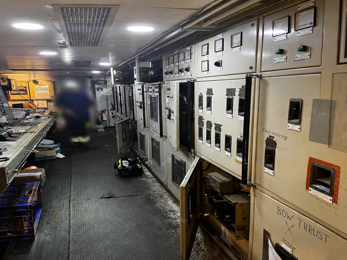
Published ongoing technical-management scope includes switchboards, distribution, automation and repair coordination. It supports system-level experience; it is not presented as a breaker-overhaul project.
See the technical-management scope →Electrical distribution and onboard control environments were reviewed during the broader multidisciplinary vessel assessment.
See the vessel-recovery assessment →Published lead-engineer experience connects control cabinets, electrical distribution and vessel systems. Historic work is attributed to the lead engineer’s experience.
See the lead engineer’s experience →Start with the information available. TESS reviews the fault, installed equipment and vessel window before confirming the attendance scope, personnel and commercial arrangements. Specialist details and attachments are optional.
Yes, within a confirmed attendance scope. Available drawings, indications, breaker/protection/control circuits, feeders and distribution interfaces guide the diagnosis. The outcome depends on access, isolation, equipment condition and parts.
Possible causes include control supply, closing coil, undervoltage release, interlocks, auxiliary contacts, protection lockout or the mechanism. TESS assesses the associated circuits before proposing replacement.
Yes. A downstream fault, insulation problem, overload, protection operation, connection condition or breaker/control fault may be responsible. Send the trip indication and load context; repeated resets are not a substitute for diagnosis.
A systematic investigation follows the distribution section, feeder and cable/load boundaries where safe isolation and vessel operations permit. Intermittent faults may require further access or monitoring; fault location cannot be guaranteed.
Where appropriate to the equipment and scope, on suitably isolated circuits. Sensitive electronics, including PLCs, VFDs, UPS units and electronic supplies, must be isolated as required before applying insulation-test voltage.
Yes: normal/emergency incomers, transfer interfaces, control supply, breaker/interlock circuits and essential feeders can be assessed. Diesel-engine, fuel, cooling and internal alternator problems require the relevant separate scope.
TESS can review indications/events, control supply, trip circuits and the breaker interface. Setting changes require authorization and an engineering/OEM basis. Specialized injection testing or protection studies are confirmed separately.
Replacement or retrofit can be assessed. Ratings, breaking capacity, protection, control voltage, mounting/cradle, bus connections, auxiliaries and interlocks must be checked; direct interchangeability is not assumed.
Yes, TESS can coordinate vessel-side execution in Panama within the confirmed scope while the manufacturer or specialist supplies technical guidance. This does not imply OEM authorization.
Vessel-side supply acceptance, breaker, phase-sequence, cable, interlock and transfer interfaces can be assessed. Compatibility depends on both the vessel design and the available port-side supply.
Load, phase imbalance, connection resistance and equipment condition can all contribute. Connection work requires appropriate isolation. Thermal inspection is included only when suitable equipment and scope are confirmed.
Many diagnostic or localized scopes can fit a short call. Completion depends on the fault, access, safe isolation, drawings, parts, equipment and operational constraints; the attendance window alone does not determine the outcome.
TESS can assess targeted switchboard retrofit and coordinate replacement or distribution renewal after diagnosis. Broader vessel-wide, multi-system modernization is developed as a separate project.
High-voltage scope is assessed case by case depending on the voltage level, installed equipment, vessel procedures, qualified personnel, required test equipment and the work to be performed.
Send the fault indication, equipment details and ETA. A prepared diagnosis defines what can be restored, which component is needed and when OEM support or a targeted retrofit is justified.