The minimum useful picture
Vessel, current location, ETA / attendance date, affected equipment or system, exact alarm or indication problem, and expected versus actual value or state.
PANAMA · ONBOARD ALARM & MONITORING TROUBLESHOOTING
Wrong reading, repeated alarm, missing channel or unstable signal? Send the alarm text, system or maker, expected versus actual indication, available photos or drawings and the vessel ETA. TESS can pre-assess the likely signal chain and prepare qualified onboard troubleshooting in Panama.
Alarm screenshot, equipment photo or drawing is enough to start. Complete documentation is not required for the first review.
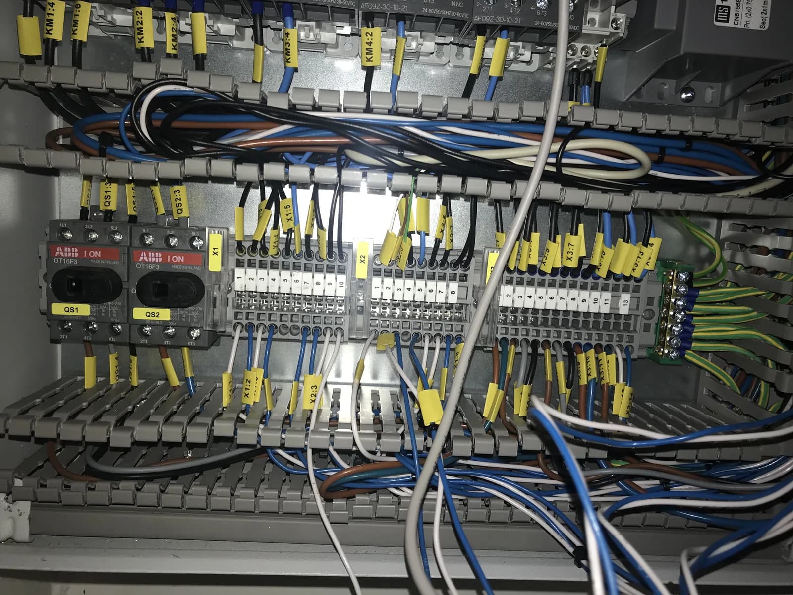
A wrong indication does not automatically mean a bad sensor. The fault may be in the process condition, sensor, transmitter, power supply, wiring, signal conditioning, I/O channel, scaling, communication or display layer.
Send what you have. A short fault description and available evidence let us begin the technical pre-assessment and plan onboard attendance.
Vessel, current location, ETA / attendance date, affected equipment or system, exact alarm or indication problem, and expected versus actual value or state.
Alarm or HMI screenshot, panel or sensor/transmitter nameplate, local gauge photo, wiring or loop diagram, alarm or I/O list, manual or previous service report.
Missing technical details do not prevent an enquiry. Send the initial case first; additional evidence can follow.
A wrong alarm or indication does not automatically mean the sensor is defective.
The displayed value is the end of a chain. A failed sensor is only one possible cause. TESS traces the accessible path from the actual condition toward the displayed value or alarm so replacement decisions are based on evidence rather than assumption.
Replacing the sensor will not correct a failed signal isolator, local supply or input channel.
An Alarm & Monitoring System (AMS) brings machinery readings and alarm states to the operator. TESS investigates the complete accessible signal path onboard, according to installed equipment, access and documentation.
Machinery alarms, missing or unstable monitoring points, channel-level signal/interface faults and accessible alarm or event history. A credible process condition comes before a replacement decision.
Transmitter supply, loop power, sensor excitation, isolators, conditioners and converters. Galvanic-isolation modules and intrinsic-safety barriers are reviewed only where technically applicable and authorized.
Transmitter/input ranges, engineering units, channel and HMI scaling, and conversion logic. One smart-device interface may be assessed; a whole network, remote-I/O rack or project fault needs PLC / HMI support.
HART, Modbus, CAN/CANopen, Profibus, Profinet or proprietary serial links may be present. Required specialist instrumentation and software interfaces are confirmed during technical pre-assessment according to the installed system and fault.
A normal local reading and an abnormal remote value can point to different parts of the signal path.
An available local reference shows a plausible process condition. Its suitability and the operating condition still need to be considered.
Compare the sensor/transmitter, local supply, wiring, isolator, conditioner, I/O channel, scaling and display/interface.
If you need selected technical information ashore, assess a B⋮Connect remote layer. Onboard alarm, sensor and signal diagnosis retains its scope here. B⋮Connect remote monitoring →
Signal type, range, supply and interface depend on the installed equipment. The scope below is confirmed for the actual installation.
Lost/open loop, local power, damaged wiring, poor terminations, isolator/conditioner or input faults, range/scaling mismatch and grounding/shielding issues. Other installed signals may include 0–10 V, resistance, digital inputs, pulse/frequency and potentiometric signals.
Pt100, Pt1000 where relevant, 2/3/4-wire RTDs, temperature switches and transmitter-based measurement. Open, unstable, fixed or implausible values are investigated. Thermocouples require the correct type, polarity, extension wiring, input/range and cold-junction implementation.
Pressure switches/transmitters and differential pressure; float, hydrostatic, capacitance, ultrasonic or radar level where applicable. Ordinary bilge, service-tank, freshwater, sewage and ballast indication is reviewed within its installed function.
Magnetic pickups, proximity/limit switches, pulse/frequency and position indication, plus selected installed flow switches/transmitters. Basic condition-monitoring signal/interface diagnosis does not include vibration analysis or predictive-maintenance assessment.
The symptom may be at the operator interface: lamp/LED, horn/buzzer, acknowledgement, reset, lamp test, relay indication, a permanently active/dead channel, or disagreement between main panel and repeater. Engineer-call and alarm-transfer interfaces are assessed where appropriate.
Alarm acknowledgement does not prove that the physical fault is cleared. Reset behavior must follow the installed system logic and valid conditions.
Start with the signal’s purpose, then the failed layer. Monitoring channels, machinery functions and the automation platform need distinct scopes.
Incorrect temperature alarm, pressure on the AMS, tank level, valve-position indication only, or RPM used only for monitoring: trace the alarm and monitoring channel here.
Temperature prevents automatic start; pressure controls compressor loading; level controls a pump sequence; or valve feedback blocks operation: Machinery Control & Automation owns the functional fault.
Machinery Control & Automation →Unexplained alarm, machinery stopped for an unknown reason, multiple unrelated alarms or a whole Integrated Automation System (IAS) issue: start with Rapid Troubleshooting. Generator PMS, synchronization and load sharing also start there.
Rapid Troubleshooting →CPU STOP, HMI runtime/application failure, offline remote-I/O rack, PLC/network failure or software/project recovery. A failed proprietary AMS controller may need this specialist and OEM coordination.
PLC / HMI Specialist Support →A whole alarm cabinet dead because the feeder is unavailable belongs to distribution. One transmitter loop without local instrument power can remain in the monitoring-channel investigation.
Switchboards / Power Distribution →VFD trips, motor phase/current faults and internal drive/encoder feedback belong to drive support. A wrong current, bearing-temperature or RPM indication used only for monitoring belongs here.
VFDs / Drives / Motors →Sensor or controller faults serving cooling, refrigeration or climate-control function belong to the dedicated HVAC and refrigeration scope.
HVAC & Refrigeration →Fire/gas, cargo gauging, hazardous-area, protection and regulatory functions need case-by-case specialist review. Identify the equipment and function before agreeing attendance.
Scope and safety boundaries →Diagnosis can justify a sensor, switch, transmitter, supply, isolator, conditioner, converter, barrier or terminal/interface component. Supported I/O, alarm, annunciator, repeater/display and controller components require system compatibility review.
The same part or a documented OEM-approved successor, subject to identification and availability.
Review supply, signal and loop type, range/units, accuracy/response, electrical and process connections, pressure/temperature/environment/IP ratings, scaling and controller compatibility. Applicable marine/type or hazardous-area approvals must be preserved.
May involve wiring, supply or signal conversion, range/scaling, mounting or process-connection changes, documentation and functional tests, with OEM/Class review where required.
The same range does not establish compatibility. A replacement decision should follow the failed layer and the installed system requirements.
Fire certification, gas calibration, oil-mist detectors, cargo gauging/safety, propulsion or generator protection, boiler/burner safety, OWS 15 ppm compliance, BWMS and hazardous-area instruments are not automatically included.
Troubleshooting and calibration are not the same service. TESS can investigate whether a field signal or displayed value is credible and compare available local and remote indications. Formal certified or traceable calibration is confirmed separately when required by the equipment, owner, OEM, Class or regulation.
An alarm does not necessarily mean a shutdown, and a shutdown input is not merely another alarm point. Safety-related functions may need machinery-control support, OEM or safety specialists, vessel authorization and Class involvement where applicable.
Accessible settings can be compared with approved documentation. Any agreed change records the point/channel, old and new value/state, technical basis, authorization, manual/OEM reference where applicable and test result. Limits are not widened simply to suppress nuisance alarms.
Safety-critical, pollution-control, fire, gas, cargo and type-approved treatment systems are assessed case by case according to the installed equipment, vessel procedures, regulatory function, OEM requirements, approval status and available specialist support.
Work is performed with vessel authorization and the applicable onboard safety controls. Live electrical circuits, process pressure, temperature, automatic machinery, stored energy and hazardous-area instrumentation require appropriate isolation, permits and specialist procedures. Alarm, trip and shutdown inputs are not bypassed simply to suppress an indication or keep machinery running.
Proprietary knowledge can remain with the OEM while TESS provides an agreed technical interface onboard. Access, documentation, software and specialist availability determine the scope; this does not imply OEM authorization.
Proprietary software, firmware, approved configuration, documentation, replacement guidance and remote specialist support remain with the appropriate provider.
Within the approved scope: identify equipment, capture readings, compare local and remote condition, inspect accessible wiring/supply/interfaces, perform OEM-directed checks and replace approved components.
Authorize access and work, agree operating conditions and tests, and receive findings, remaining limitations and the next action.
A Panama port call can be enough to identify the failed layer even when complete restoration requires a later spare part or OEM action. Sending the fault information before arrival increases the amount of useful work that can be prepared in advance.
Identify the system/channel, review the alarm, compare available local/remote condition and inspect the accessible path to narrow the sensor, wiring or system layer.
Deeper signal tracing, local instrument-supply and channel/interface diagnosis, accessible component replacement and agreed alarm/indication functional tests.
Multiple-channel diagnosis, wiring repair, sensor/transmitter or supported I/O/module replacement, OEM coordination and repeated operational tests.
Obsolete alarm-panel renewal, AMS migration, instrumentation renewal or broader monitoring-system modernization.
Planning bands describe possible scope, not completion promises. Access, vessel operation, spares, permissions and OEM dependencies determine the achievable work.
Attendance purchases qualified diagnostic effort, not guaranteed restoration. Findings should make the next technical and commercial decision clearer.
The fault is corrected and agreed functional operation verified.
The failed layer or probable fault is narrowed sufficiently for the next action.
Evidence justifies component or interface replacement and a compatible spare can be defined.
Lifecycle condition makes local repair technically or commercially unsuitable.
Where applicable, the report records system/maker/model, affected channel, reported and as-found values, available local reference, sensor and signal type, supply/interface/wiring findings, component changes, tests, limitations, recommendations and spares. This provides continuity for later port calls and repeat fleet support.
Repeated channel failures, unavailable modules or an unsupported alarm/monitoring platform may indicate that the problem has moved beyond local repair. TESS can define the immediate fault first and, where justified, route the system into a controlled modernization scope.
Discontinued sensors/transmitters, obsolete proprietary modules, unsupported HMI/I/O, degraded wiring, undocumented configuration and lack of spares are reasons to assess lifecycle options.
Control cabinets, vessel systems, monitoring/alarm integration and commissioning across newbuild and modernization projects delivered under the leadership of our lead engineer.
View the documented project →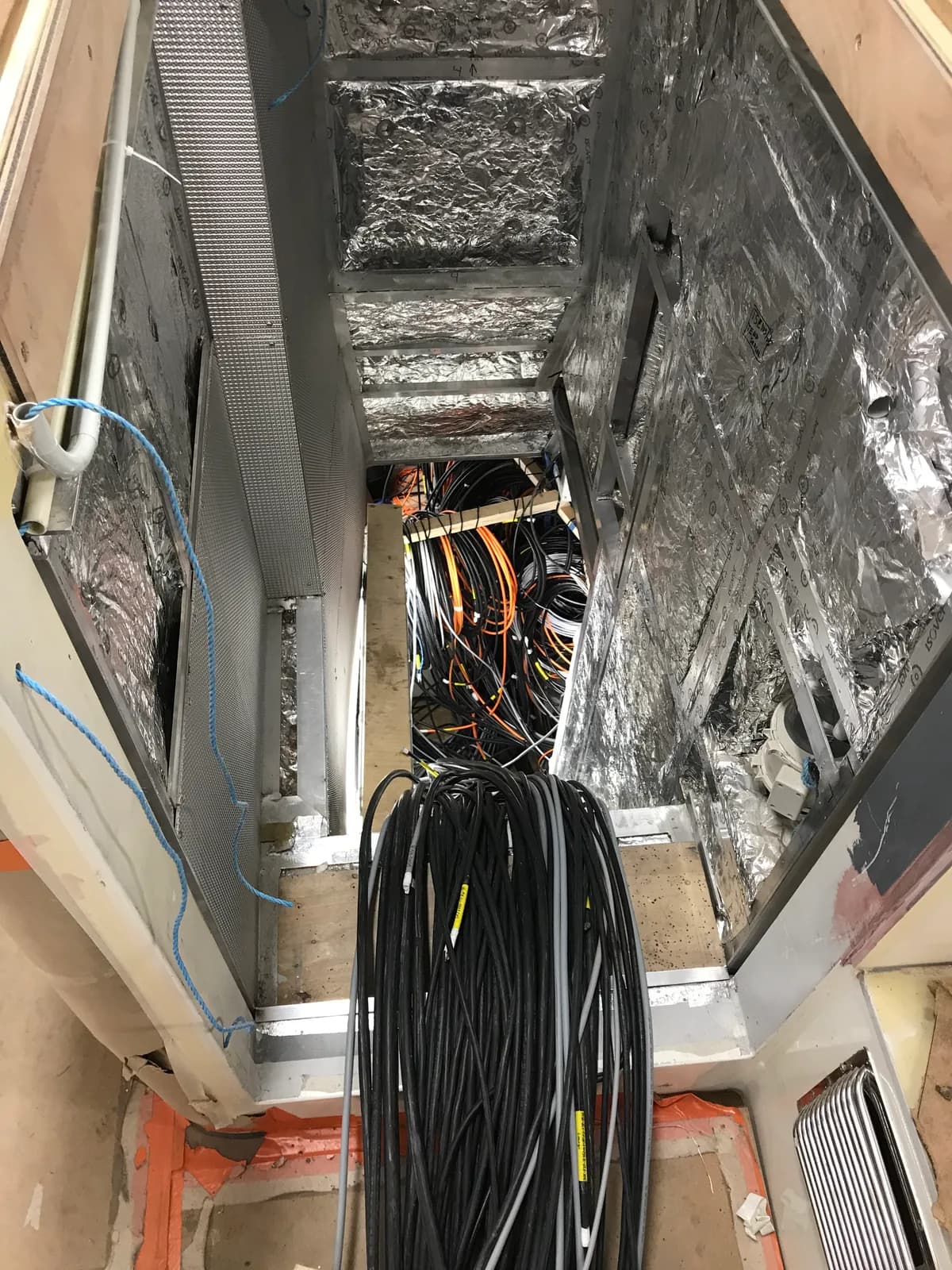
Send the problem before arrival: enquiry → technical pre-assessment → prepared onboard attendance. Include the system/maker, alarm or reading, expected versus actual value and local indication if available. The technical next step and commercial arrangements follow review.
Yes, within a confirmed scope based on installed equipment, access and documentation. Send the system, symptom, vessel location and ETA so the accessible signal path and attendance needs can be reviewed before arrival.
No. First establish the actual condition. Sensor, transmitter, supply, wiring, conditioning, I/O, scaling, communication or display may explain the symptom. Trace the signal before replacing the sensor.
Compare what the two indications represent, then investigate the accessible signal path to the remote value. This does not immediately establish a mechanical or process fault.
TESS can assess installed loop faults within the agreed scope, including power, wiring, conditioning, input channels and scaling. Instrumentation and interfaces are confirmed during pre-assessment.
RTD, temperature-transmitter and thermocouple channels can be assessed subject to installed type, wiring, input configuration and available access. Formal calibration is a separate requirement.
Where diagnosis and compatibility review justify it, TESS can arrange a suitable component and agreed replacement/testing scope. Range alone does not establish compatibility; supply, signal, connections, ratings and approvals also matter.
Review replacement compatibility and the rest of the chain, including local supply, terminations, isolator, input channel, range/scaling and display. Another sensor replacement may not address the fault.
A shared supply, module, communication path or platform fault may be involved. A failed rack/network/platform needs PLC / HMI support; an unknown or wider integrated-system issue starts with Rapid Troubleshooting.
Troubleshooting and comparing readings do not automatically include certified or traceable calibration. Any formal calibration requirement, method and suitable provider are confirmed separately according to equipment, owner, OEM, Class or regulation.
Accessible channel-level work may be possible after review. Proprietary software, passwords, configuration access and manufacturer support cannot be assumed. TESS can coordinate agreed onboard checks with the OEM; universal platform support is not offered.
Accessible values can be checked against approved documentation. Any justified change requires an agreed technical basis, authorization, documentation and testing. Arbitrarily widening a limit to hide an alarm is not a repair.
Fire/gas and other safety or regulatory systems are assessed separately, case by case. General alarm troubleshooting does not imply fire-system certification, gas-detector calibration or authorization to program safety systems.
A port call may allow fault isolation or an agreed repair, depending on access, operating conditions, spares and OEM support. Sending evidence and ETA beforehand helps prepare useful work; restoration within the call is not guaranteed.
No. Inputs are not bypassed merely to silence an indication or keep machinery running. Safety-related work requires vessel authorization, appropriate isolation and procedures, and OEM, safety specialist or Class involvement where required.
Start with what you have. TESS can review the evidence and prepare an appropriate onboard diagnostic scope in Panama.