WORKBOAT & COMMERCIAL VESSEL AUTOMATION

Böning Automation for Workboats & Commercial Vessels in Panama

Böning monitoring, alarms and selected control architecture for tugs, workboats, service craft, fishing vessels and selected passenger or commercial vessels, with practical onboard engineering and integration from Panama.

Operational visibility · modular architecture · project-specific integration

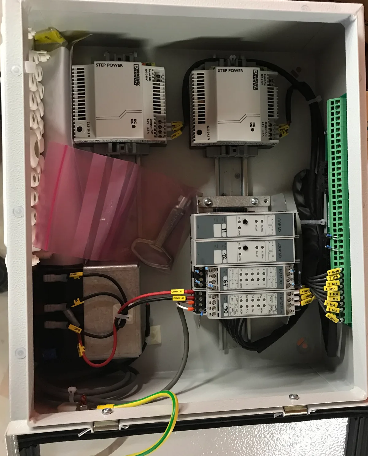
Local machinery control cabinet from a marine project
Engineering context from the project archive. Not presented as a specific OEM configuration for this service.

Built around the Work the Vessel Performs

A working vessel needs information that helps its crew understand machinery condition and vessel-system status during the actual operating day. The project may involve a compact bridge, several machinery spaces and equipment from different suppliers. Böning automation should be assessed against that practical setting, with a scope the operator can use and maintain.

Relevant applications include tugs, workboats, pilot craft, crew and service boats, utility and supply/support craft, and fishing vessels. Selected small passenger, ferry and research applications can also be reviewed where technically suitable. These segments do not have identical requirements. Duty, operating modes, installed machinery and applicable rules are more useful design inputs than a broad vessel-category label.

TESS can help a fleet or technical manager define the onboard visibility, alarms and selected control functions needed for a suitable project. The onboard architecture should reflect those operating requirements. A multi-vessel information requirement ashore follows the B⋮Connect route; a lifecycle problem in an existing installation follows the Böning retrofit route.

Tugs, pilot and service craft

Start with the information needed by the operator during vessel duties and the relationship to local machinery indications. Define useful alarms and station responsibilities without assuming that the automation system takes over propulsion, steering or other independent controls.

Fishing, utility and support vessels

Review machinery, tanks, bilges, pumps and auxiliaries against the vessel’s actual systems. Equipment packages and working arrangements vary; the project should identify the sources and functions that justify inclusion rather than collect every available signal.

Selected passenger and research craft

Assess the intended function, equipment scope and applicable requirements individually. Passenger or research use does not by itself establish platform suitability. The scope must be supported by the proposed architecture, interfaces and approval process.

What B⋮MACS Means for a Working Vessel

B⋮MACS is Böning’s modular onboard monitoring, alarm and control architecture. For a workboat or selected commercial vessel, it can bring agreed system information through acquisition and processing to the operator HMI, with interfaces and selected control functions defined by the project. Its role is to connect the required information and functions in a coherent onboard arrangement.

A useful scope might prioritize a small number of operationally meaningful systems rather than an extensive display catalogue. The vessel’s technical team should be able to relate each indication or alarm to a real source and a defined purpose. Expansion requirements can be discussed during engineering, but are not a promise of unlimited capacity or compatibility.

This offer does not position B⋮MACS as a universal replacement for a large deep-sea IAS. It does not assume LNG-carrier, cruise-ship, DP or broad power-management scope. A suitable commercial application must be established from the actual functions, installation and regulatory requirements.

From Engines and Field Signals to Operator Visibility

The architecture begins at the equipment and its available signals. Acquisition and processing convert supported information into the agreed monitoring and alarm structure. Interfaces may connect existing equipment packages, while the operator layer presents the vessel’s selected systems. Each connection needs a defined source, destination, meaning and responsibility.

The engineering review should distinguish direct field measurements from information supplied by a machinery controller. It should also identify which functions remain within an independent local system. That distinction helps the crew interpret the operator view and helps the project team define tests for normal states, alarm conditions and loss of source information.

Selected commands are a separate part of the scope. A pump-running indication does not demonstrate a start/stop interface; a generator value on a screen does not establish generator control. The approved onboard logic, equipment protections and operating permissions determine what can be included.

Working-vessel information architecture

  1. Engines / gensets / tanks / pumps / auxiliaries
  2. Field signals and supported interfaces
  3. Acquisition / processing / B⋮MACS
  4. Operator visibility / alarms
  5. Explicitly engineered selected controls
Conceptual scope, not a wiring diagram. Monitoring paths and command paths have different requirements; equipment protection remains authoritative.

Monitorable does not mean automatically controllable. A command path must be explicitly engineered, verified, permitted and consistent with vessel safety logic.

Engines, Gensets and Selected Electrical Information

Define the machinery information needed to understand operation: relevant status, measurements and alarms that the installed source can make available. An engine or genset may already have its own controller and local protection. The automation project must identify how information is obtained without treating the central display as a replacement for those responsibilities.

For generator-related information, distinguish monitoring from commands and from power-management functions. The availability of electrical values or running status does not establish synchronization, load sharing, protection or energy-management capability. Any selected control function needs an agreed interface and explicit project verification; broader claims are not part of this offer.

A fleet manager should be able to see which sources are included and which remain outside the scope. The engineering package should record the supplier inputs needed to confirm data meaning and access. Where the requirement is a machinery-control fault, the generic specialist service remains the appropriate technical route.

For an installed machinery-control problem rather than a Böning architecture project: Machinery control and automation support →

Tanks, Bilges, Pumps and Auxiliaries

Tank information, bilge states and auxiliary equipment status can be valuable when the operator needs an understandable picture of the vessel. Begin with the actual sensors, equipment controls and available documentation. Define which measurements or states are useful, which conditions need alarms and which sources require inspection or improvement before integration.

A tank level is useful only when its source, meaning and operating context are understood. A pump status may describe a command, feedback or another condition; those are not interchangeable. The project should identify what each displayed item represents so that the crew does not infer equipment behavior from an ambiguous label.

Tanks and bilges

Review the available sensors and their relation to the information requested. Agree the displayed states or measurements and the alarm conditions in scope. The installation and test plan must verify the chain from source to operator, including how unavailable information is recognized.

Pumps and auxiliaries

Separate equipment state, alarm and command requirements. A selected command requires the appropriate interface, feedback, interlocks and permissions. Local equipment protection and operating procedures continue to govern the machinery.

Serviceable installation

Allow for access to sensors, terminals, cabinets and interfaces. Useful documentation should let the crew and future service personnel trace the agreed signal path and understand the division between the automation package and the equipment OEM.

For generic sensor, channel or alarm-system diagnosis: Alarm, monitoring and sensor service →

Third-Party Integration: Confirm the Interface, Then the Scope

Working vessels often contain machinery and auxiliaries from several manufacturers. Integration can be considered where technically feasible and where protocols, signals, documentation, access rights and safety logic permit. The review must identify the actual interface available on each installed unit, not simply the manufacturer’s name.

For each proposed connection, define the information or function required, the party responsible for the source configuration and the test that will demonstrate the result. An interface may expose a limited set of data without supporting commands. If proprietary access or OEM assistance is required, include that dependency in the project plan and quotation.

TESS remains multi-brand, including support for Siemens, Schneider Electric and other environments where technically viable. Naming an installed platform does not claim authorization from its manufacturer. Existing equipment can be assessed on its merits; a Böning project does not require assuming that every other system must be replaced.

How TESS Delivers from Panama

Begin with the vessel type, operating requirement and available system information. TESS can review the intended scope and prepare an onboard survey to confirm sources, interfaces, operator locations and installation constraints. The survey should produce decisions or clearly identified dependencies, so the next engineering step is useful to the fleet manager.

Depending on contract, TESS may develop scope and interface definitions, coordinate equipment supply, organize onboard installation and support testing and commissioning. Böning remains responsible for its proprietary product engineering, firmware and product documentation. Other machinery OEMs retain responsibility for their own equipment and agreed interface inputs.

Execution must fit the vessel’s service schedule and available access. Agree which systems can be worked on, which tests need vessel participation and how handover will be documented. Panama-based support helps coordinate attendance, but does not establish a guaranteed response time or allow project testing to bypass operating constraints.

  • Define the operational information and selected functions
  • Survey equipment, signals and installation access
  • Resolve supplier and OEM interface responsibilities
  • Coordinate installation and the agreed test programme
  • Document commissioning results and support arrangements

For wider technical coordination across suppliers or work packages: Engineering & Superintendence →

Newbuild or Existing Vessel

In a newbuild, source interfaces, operator views and installation routes can be coordinated with machinery procurement and yard design. The automation scope should be visible in supplier requirements early enough to confirm that the necessary information and functions are available. Testing responsibilities should be agreed alongside those requirements.

An existing vessel needs a survey of its installed architecture, including modifications and gaps in documentation. A technically suitable source may be retained, but that decision needs evidence. When lifecycle, obsolescence or migration is the main problem, the Böning retrofit assessment defines the retention decisions and controlled transition.

For retention, replacement and migration decisions: Böning existing-system modernization →

For selected information needed by a fleet team ashore: B⋮Connect vessel and fleet visibility →

Class and Safety: Requirements Belong to the Vessel

Identify the vessel, flag and Class requirements at the start of the project. Relevant component approvals do not automatically approve the complete installed system. The project needs a defined path for reviewing architecture, functions and test evidence, with approval retained by the applicable Class or authority.

TESS may coordinate documentation, Class interfaces and project testing within the contracted scope. Local controls, machinery protection and vessel safety logic remain authoritative. Monitoring and selected control must be assessed separately, especially when several systems share an operator location or network connection.

Where system or network interfaces require it, review access control, credentials and the project’s cybersecurity requirements. A later remote extension needs its own deeper assessment of exposed data and connectivity. No blanket cyber or system-approval claim is made for an unassessed installation.

Evidence from Marine Automation Integration

The published marine automation integration case describes bridge consoles, control cabinets and integration work delivered under TESS’s lead engineer. The attribution remains lead-engineer experience before or outside TESS corporate delivery. It provides practical context for drawings, fabrication, cabling and functional coordination; it is not presented as a verified Böning workboat deployment.

For a new commercial-vessel enquiry, proof should support the method and relevant experience without substituting for a vessel-specific assessment. A different workboat may have different OEM interfaces, installation constraints and approval requirements. TESS will define the applicable scope from the equipment and operating need actually presented.

Review the documented experience and attribution: Marine automation integration case →

DEFINE THE NEXT ENGINEERING STEP

Commercial Vessel Automation Assessment

Send the information available. TESS will review the objective, installed system and project window to propose the next technical assessment. Scope and commercial terms are agreed after that review; a complete specification is not needed to start the enquiry.

  • Vessel type, duty and newbuild/existing-vessel status
  • Machinery and automation maker/platform, if known
  • Systems requiring monitoring, alarms or selected control
  • Available drawings, operator-station photos and the planned attendance window
Which working vessels are relevant?

Tugs, workboats, pilot, crew/service, utility/support and fishing vessels can be assessed, as can selected small passenger, ferry or research applications. The duty, equipment and requirements determine suitability; the vessel label alone does not.

Can machinery and generator data be shown?

Selected data may be included where the source interface supports it. Monitoring a genset does not establish power management, synchronization, protection or control capability. Those functions must not be inferred from a display.

Can tanks, bilges and pumps be included?

They can be assessed against the installed sensors, controls and required functions. The project defines measurements, states, alarms and any selected commands separately, then verifies the agreed path to the operator.

Does an equipment indication enable control?

No. Indication may come from a read-only or limited interface. Commands need an engineered output path, onboard logic, feedback, permissions and safety verification. Local protection remains in force.

Can existing third-party equipment remain?

Potentially, after condition, interfaces, documentation, access and support are assessed. Reuse is project-specific. If the main decision concerns legacy equipment and migration, use the Böning retrofit assessment.

Can a fleet manager view several vessels ashore?

That is a separate B⋮Connect assessment for selected vessel information, subject to sources, connectivity and authorized access. It does not automatically come with every onboard B⋮MACS installation.

Is the complete installation automatically Class-approved?

No. A component approval and approval of the installed vessel system are different. The project must satisfy the applicable vessel, flag and Class requirements, with approval retained by the relevant authority.

What information starts the assessment?

Send vessel type and duty, the required information or functions, current equipment details and the intended window. Drawings and photos help identify interfaces. Unknown technical details can be resolved through a planned survey.
Fields marked * are required. Technical details may be left blank if unknown.

Describe the outcome you need and the current system, if known. Do not include passwords or access credentials.
Add vessel and project details
Optional: up to 5 JPG, PNG, WebP, PDF, DOCX or XLSX files, 4 MB total. For larger documents, send the enquiry first and agree a transfer method.

Back to Böning Marine Automation →